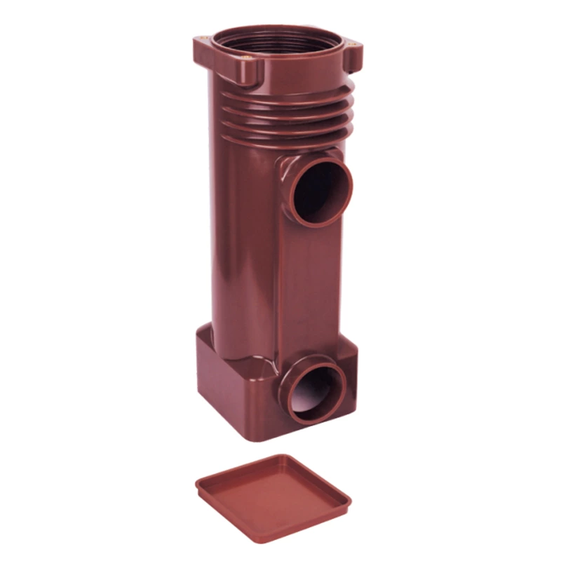
High Voltage Insulator Structure And Material Requirements
High Voltage Insulator Main body requirements
±800kV high-voltage insulators use synthetic jackets, and the core rods are epoxy glass fiber reinforced resin.
End flanges
a) The top flange is made of 0Gr18Ni12 anti-magnetic stainless steel, and the remaining flanges can be made of malleable cast iron or ductile iron, and hot-dip galvanized. The tensile strength of the metal flange should be no less than 450 MPa, and the elastic modulus should be no less than 120MPa. The thickness of the galvanized layer of ductile iron or other malleable cast iron should be no less than 85µm (600g/m2).
b) Each unit is equipped with necessary threaded connectors, and the bolt size should take into account the need to add a 12mm pad between the two units, and the length is 12 mm longer than the conventional size. All connectors require hot-dip galvanizing. The strength grade of the galvanized bolts should be no less than grade 7.8, and the elastic modulus should be no less than 200GPa.
In order to prevent loss and the need for destructive acceptance tests, the supplier must increase the fastener margin by 5%.
Shielding ring
The top of the ±800kV insulator is designed with two electric field shielding rings, and the large shielding is provided by the reactor manufacturer. However, the small shielding rings installed at both ends of the insulator to prevent partial discharge and leakage tracking on the surface of the insulator end are provided by the insulator manufacturer. The lower end (grounding end) of the high-voltage side insulator should also be equipped with a small shielding ring to control the electric field strength on the insulation surface below 400v/mm.
The small shielding ring is within the shielding range of the large shielding ring, so the diameter of the tube can be appropriately reduced so as not to excessively affect the size of the large shielding ring.
The small shielding ring installed at the upper end is in the alternating magnetic field generated by the harmonic current of the smoothing reactor. In order to prevent a large induced current from appearing in the shielding ring, it should be designed as a non-closed structure. For easy installation, the lower end shielding ring should also be designed as a two-half combination.
The shielding ring is a consumable part and is easily damaged during the installation process. The supplier should provide spare parts for the various specifications of shielding rings supplied, 2 sets for each specification.
